In my previous articles, I mentioned a few concepts that may be new to you, like device tree and overlay. If you thought you could just ignore them and keep on learning how to program device drivers with Raspberry Pi… you were technically right, at least in some cases, and with certain devices. But believe me: device trees are powerful, and you will probably have to master them anyway if you want to become an embedded Linux developer. And not only that, if you want to send your drivers upstream, often you will have to provide bindings for the devices as well, which are closely related to device trees. Just stop procrastinating and learn with me.
Writing a complete device tree that describes a SoC is a big endeavor and definitely overkill to program a driver for a specific device. I am pretty sure you are not planning to describe your complete system from scratch, are you? Instead, you usually just want to add some new device to the system, or modify how some hardware of that system behaves. What you are looking for is an overlay, and that will be the main topic in this article. I am going to show you how to apply overlays to device trees, and how to write your own.
I don’t want to leave complete beginners behind, so let’s see what device trees and overlays are in the first place.
Content:
- Bare minimum aout device trees
- Analyzing a real overlay: htu21 I2C humidity sensor
- Enough theory: applying overlays to the Raspberry Pi
- Writing a new overlay: step by step
1. Bare minimum about device trees
In this section, I am going to summarize the key points we are going to need later for the examples, which are mainly tailored for Raspberry Pi. If you want to get deeper (at some point, you should), please take a look at proper documentation, and let me focus on the fun stuff. What is proper documentation?
- Device tree Specification from devicetree.org
- Kernel documentation
- Raspberry Pi documentation
I would recommend you to keep those sites open while working with device trees, because they will save you from dumb answers by your preferred AI.
A device tree (DT) is nothing more than a description of some piece(s) of hardware. The kernel uses that description to find out what devices form the system, where they are located, and what properties they have.
Is that the only way to find devices? Of course not. Are you going to add all possible USB devices to your DT? No, because USB (and other buses like PCIe) supports enumeration (some magic to identify devices automatically). I even showed you how to load I2C drivers from userspace, do you remember? Cool thing, yet not that useful in production. If you were planning to program a service to automatically load the driver at run time with that mechanism, forget such a hacky idea right now.
There are also architectures (being x86 a good example) that don’t require DTs (ACPI is another option), but in the embedded world you will be working with DTs all the time. The most popular architectures like ARM (e.g. your Raspberry Pi) and RISCV use DTs, so it is clear that you will have to deal with them.
The hardware description in a DT follows a node-based hierarchical structure, starting from a root node, all the way down to buses and the devices connected to those buses. Every node is just a description of one of the components of the system (a CPU, an SPI bus, etc.), where some relevant properties are listed. We will see a few examples later.
DTs are described in Device Tree Source (DTS) files (.dts) that might include some Device Tree Source Include (DTSI) (.dtsi files that define common hardware present in several designs). Pretty much like a C program with descriptions instead of instructions.
On top of that, Device Tree Source Overlays (DTSO or DTO, or simply overlays, files with .dtso extension) can extend the DT if some extra hardware (maybe model-dependent, maybe optional) is added to the “core” system.
That is the theory, but in reality many designs don’t use any .dtso, and Raspberry Pi is a good example of a design where everything is a DTS. Anyway, we are going to add new devices to an existing system, so overlays are exactly what we are looking for. The internal structure is what really matters, not the file extension.
All the files that form the complete DT must be compiled to generate a blob (.dtb), that is actually what the kernel will use to figure out the hardware present on the system. As you can imagine, there are also overlay blobs (.dtbo) to account for that “extra” hardware.
2. Analyzing a real overlay: htu21 I2C humidity sensor
Now that you know what we are talking about, we are ready to work with real DTOs. By the way, if you want to see complete DTs, you will find plenty of them in the Linux kernel under arch/{arm,arm64,ricv,"others"}/boot/dts/.
First, we are going to take a look at an example with one of the overlays available in the Raspberry kernel fork. You will find them under arch/arm/boot/dts/overlays.
We are going to use i2c-sensor as an example, because it includes many sensors at once, so with a bit of luck, you might find one of them in your nearest electronics store for a couple of dollars. If that is not the case, it does not really matter. You can load the overlay with and without hardware… if you load a virtual device with the right I2C address. If you read my last article about I2C on Linux, you know how to do that ![]()
Fortunately, I have one of the sensors included in that overlay: the humidity and temperature sensor htu21.
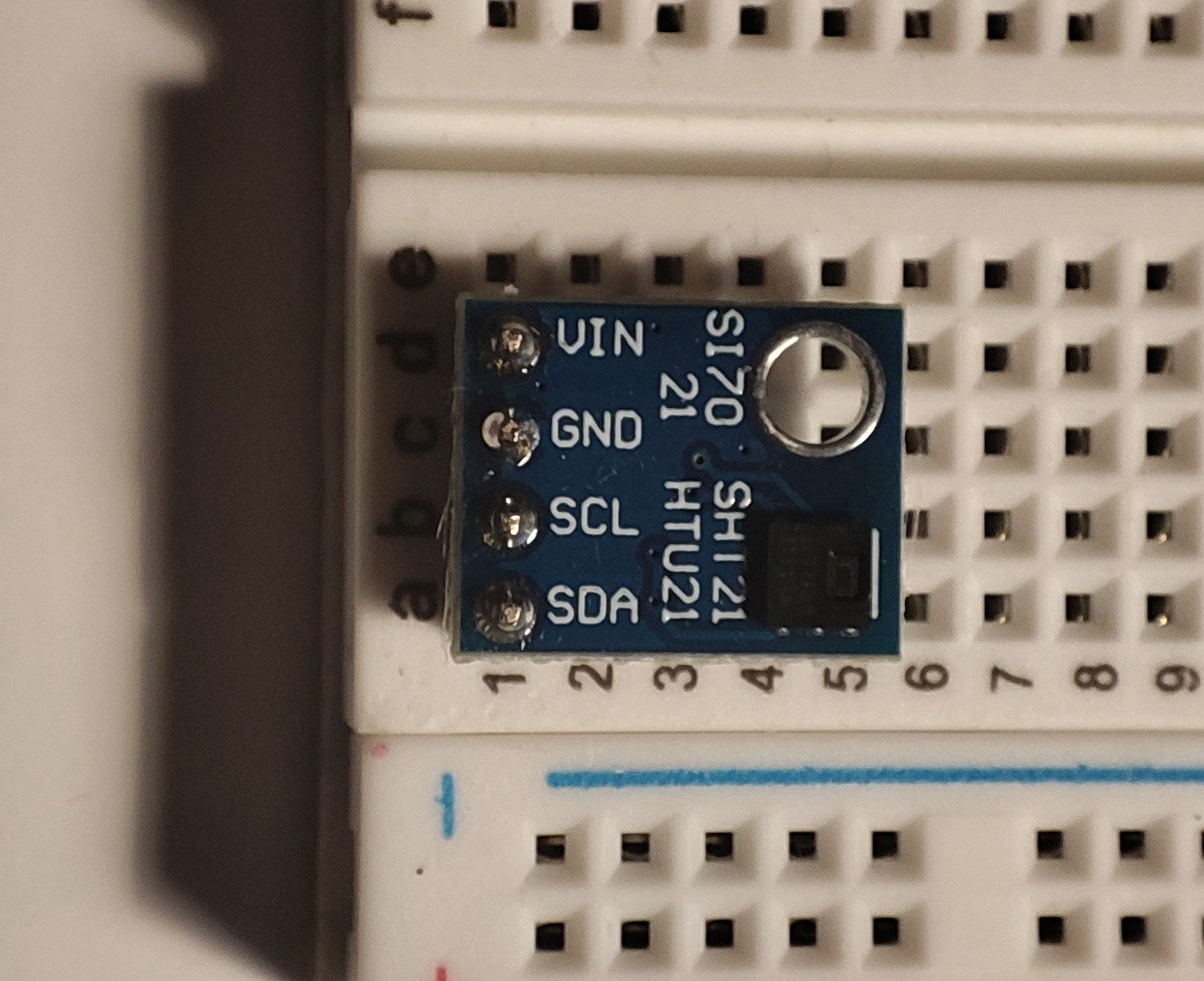
By the way, I found this little bug in its driver, so I fixed it and sent the patch upstream. If you are using v6.7 or later, it should be applied already. You might also find a bug in a driver you are using for some piece of HW and then fix it. Awesome, but don’t forget to send the fix upstream, so everyone can profit from it. How can you do that? Read the second and third articles of my series about how to become a Linux kernel contributor. Easy peasy lemon squeezy! ![]()
The htu21 can be found in i2c-sensor-common.dtsi:
// Definitions for I2C based sensors using the Industrial IO or HWMON interface.
/dts-v1/;
/plugin/;

#include <dt-bindings/gpio/gpio.h>

/ {
	compatible = "brcm,bcm2835";

	/* some other fragments starting from 0 */

	fragment@4 {
		target = <&i2cbus>;
		__dormant__ {
			#address-cells = <1>;
			#size-cells = <0>;
			status = "okay";

			htu21: htu21@40 {
				compatible = "meas,htu21";
				reg = <0x40>;
				status = "okay";
			};
		};
	};

	/* some other fragments and magic we don't care about yet */
};
The structure of the overlay is as follows:
- /dts-v1/: to tell dtc the file is a version 1 dts (by default version 0 is taken, which is obsolete).
- /plugin/: to indicate that this is an overlay, and not a DT.
- includes: add common functionality. In this case, gpio.h adds constants like GPIO_ACTIVE_HIGH.
- root node (/ { }): the node that contains the nodes we want to add/modify. A compatible property indicates the target DT.
- fragments: child nodes that consist of a target property and a node called either __overlay__ (i.e. included by default) or __dormant__ (i.e. excluded by default) with the stuff that will be added to the target.
In this case, we have fragment@4, and its target is i2cbus. We have a __dormant__ node, which means it will not be included by default (we will see how to include it soon). Looking at that node, we can see that we are going to add a node to the I2C bus (the htu21), but also mark the I2C bus as “okay” (in case it was not enabled).
Watch out! Heavy stuff is coming!
#address-cells and #size-cells are less intuitive at first glance… But please, do not get stuck here. Usually you don’t have to worry much about them, just copy and paste because those values are bus-specific. But if you wonder, they refer to the reg property of the child node and describe how the child node should be addressed: #address-cells specifies the number of u32 cells required to encode the address field, and #size-cells specifies the number of u32 cells to encode the size field. WTF am I talking about?? In its general form, the reg property encodes <address,length> pairs to account for address regions in certain devices. For example, you could describe a device with a memory-mapped IO register block that starts at 0x4242 and is 66 bytes long like this: reg = <0x4242 0x42>;. In that case, you would have #size-cells = <1>;. When #size-cells is zero, length is omitted, and that is why we only write reg = <0x40>.
Trivia: given #size-cells = <1>, what would be the right value for #address-cells if reg = <0x42 0x12345678 0x100>? If we have one u32 cell for the size (0x100), and two left to encode the address 0x421234567 (too big for one u32 cell)… #address-cells = <2> should do the trick.
Too much digression for a simple I2C device… We need a single address cell to encode any valid I2C address i.e. #address-cells = <1>, and there is no memory mapping, only access via I2C i.e. #size-cells = <0>.
Now let’s focus on the htu21 node, which is the one that describes the I2C device. What do we have there?
-
htu21: a label that can be used as a reference or phandle in case the node must be referenced somewhere else. The
&i2cbusreference we saw before was a phandle too. - htu21@40: the node name, which by convention includes the device address in the form NAME@ADDR.
- compatible = “meas,htu21”: the string required to match the device with its driver. Yes, the driver will include the same “compatible” string and if a match happens, the driver will try to manage the device. If you read my article about I2C on Linux, you have already seen a match mechanism. Note that the compatible string usually follows the XX,YY pattern, where XX is the name of the manufacturer and YY the device name.
- reg = <0x40>: the I2C address of the device.
-
status = “okay”: the device is ok… reassuring info is always good
 It could also be “disabled” if it is not operational for some reason (e.g. disabled by default and then enabled by means of overlays).
3. Enough theory: applying overlays to the Raspberry Pi
Now we would like to add (i.e. apply) the node we just saw to the whole system description (i.e. device tree), so the kernel can load the proper device driver automatically. Like almost everything in the Raspberry world, it is pretty simple.
The easiest approach is using dtoverlay (for more information, man dtoverlay), either as a regular command to apply overlays at run time, or including the overlays you are going to need in your config.txt. Don’t you have to compile the overlay first? Definitely, but if you read my article about how to configure the Raspberry Pi, it has already been done when the kernel was built (check the command we used: make ARCH=arm64 CROSS_COMPILE=aarch64-linux-gnu- Image modules dtbs -j$(nproc)). You could also build single overlays with dtc (sudo apt get device-tree-compiler), but it gets annoying once you have includes because you need the cpp preprocessor, so I would stick to the simpler make dtbs.
This is how you can load an overlay:
-
At run time. Run the following command:
sudo dtoverlay i2c-sensor htu21Let’s see if we succeeded with the same tool and the -l argument:
 dtoverlay -l
 Overlays (in load order):
 0:  i2c-sensor  htu21=true
Bonus: you can see all the overlays available with
dtoverlay -a. This command will display an asterisk in front of the overlays that were loaded at run time. Some (or many) of the overlays from the list might have been loaded at boot time, so you will not need/be able to reload them.Why did we need to tell what specific device we wanted to load? Because if you remember, i2c-sensor uses
__dormant__nodes, so you don’t load a bunch of random devices at once. That is part of the magic we ignored at the end of the overlay. Later we will use__overlay__nodes instead, and all of them will be loaded at once. -
At boot time. Add the following line to your config.txt:
dtoverlay=i2c-sensor,htu21As you can imagine, any other supported device instead of htu21 will work exactly the same.
Either way, now there should be a new entry under /sys/bus/iio/devices, and our htu21 should be ready to deliver data.
4. Writing a new overlay: step by step
We are ready to write our own overlay for a new device. For this example, I am going to use the Amphenol Chipcap 2 humidity sensor. This device is a bit more complex than the htu21 and it will give us the opportunity to go beyond boilerplate.
You will not find kernel support for the Chipcap 2 until v6.8 because my driver was accepted upstream a few days ago. If you want to give it a try, you can find it in the hwmon git repo until it gets merged.
The first thing we should do is getting the relevant information from the datasheet, which is available here. If you know nothing about hardware, reading a datasheet for the first time might be overwhelming. But just keep this in mind: we are going to describe hardware for the kernel, and the kernel does not care about its power consumption, size, or form factor. And from a DT point of view, its internal settings (registers, setup time, etc.) don’t matter either. We only have to provide the information required to find the device and communicate with it:
-
Communication protocol? I2C. Address? 0x28.
-
Any other sources of information? In this case, yes, these three signals:
- 1 ready signal: from low to high (rising edge) when data is ready.
- 2 alarms (low/high humidity): from low to high (rising edge) when an alarm occurs.
In principle, that’s all we have to describe in the node.
This device is a bit tricky (hence why I chose it ![]() ), and it requires a power cycle to enter command mode, so we will need an additional node:
), and it requires a power cycle to enter command mode, so we will need an additional node:
- 1 dedicated 3v3 regulator to trigger power cycles. We will cover this towards the end of the example.
Alright, let’s start with the boilerplate. The overlay file must be in the overlays directory, its name must be "name"-overlay.dts, and the overlay must be added to the Makefile like this: "name".dtbo. We can copy an existing overlay, rename it to chipcap2-overlay.dts, and adapt it to our needs. In the Makefile a chipcap2.dtbo entry will be added to dtbo-$(CONFIG_ARCH_BCM2835) (where all the overlays are listed).
Now you could borrow a couple of fragments from existing overlays that include I2C devices with interrupts and rename them. But as I have already done that, you can simply copy the following snippet:
/dts-v1/;
/plugin/;

/* Overlay for Chipcap 2 on i2c */
#include <dt-bindings/gpio/gpio.h>
#include <dt-bindings/interrupt-controller/irq.h>

/ {
	compatible = "brcm,bcm2835";

	fragment@0 {
		target = <&i2c1>;
		__overlay__ {
			#address-cells = <1>;
			#size-cells = <0>;
			status = "okay";

			chipcap2: chipcap2@28 {
				compatible = "amphenol,cc2d23s"; //from the driver
				reg = <0x28>;
				interrupt-parent = <&gpio>;
				interrupts = <4 IRQ_TYPE_EDGE_RISING>;
				status = "okay";
			};
		};
	};

	fragment@1 {
		target = <&gpio>;
		__overlay__ {
			chipcap2_pins: chipcap2_pins {
				brcm,pins = <4>;
				brcm,function = <0>; /* in */
			};
		};
	};


	__overrides__ {
		ready_pin = <&chipcap2>, "interrupts:0",
		            <chipcap2_pins>, "brcm,pins:0";
	};
};
Wow, we have stolen a lot of new stuff! Let’s see what we got:
- A new include
irq.h. We need it to get the definition of IRQ_TYPE_EDGE_RISING. You could use hard-coded integers instead, but definitions look cleaner. - An
interrupt-parentproperty in the device node. It specifies the controller to which the interrupt is routed. Usually you will connect the interrupts to the GPIOs of the Raspberry Pi, so you will assign a phandle to gpio. But for example, if you are using a GPIO expander with interrupt output, you might have to reference it instead. - An
interrupsproperty in the device node. To indicate what pin of the controller is receiving the interrupt and its trigger type. I chose GPIO 4 and as we saw earlier, the trigger type is low-to-high edge. - A new fragment
fragment@1. The target of this fragment isgpioand it sets the pin I chose to be an input. Such gpio node modifiers are also useful to select pin alternate functions withbrcm,functionor pull up/down resistors withbrcm,pull, which is something we don’t need here. You will find some examples of that in other overlays. - A weird node called
__overrides__. That is the magic node. We can use it to enable/disable nodes (likei2c-sensordoes), but also to override the default pins by passing a different pin as a parameter. That is especially handy during development or if several devices use the same pin by default and you don’t want to modify the overlays. Just define a new property with the name you want and phandles to the device and device pin nodes. And the zeros? Keep on reading.
You might have noticed that we still have a single interrupt: the ready signal. Actually, it could be any of the interrupts, right? There is still nothing here to tell the difference. How do we add the low/high humidity signals? Easy: adding them to the interrupts property and configuring them in the fragment referencing the gpio. And how does the driver know what they mean? We will use the interrupt-names property for that, which I did not find in any overlay, but it is documented in the resource-names bindings. I am going to assign the pins 5 and 6 for the new interrupts, but also give the chance to override the defaults. All things considered, the overlay should look like this:
/dts-v1/;
/plugin/;

/* Overlay for ChipCap 2 on i2c */
#include <dt-bindings/gpio/gpio.h>
#include <dt-bindings/interrupt-controller/irq.h>

/ {
	compatible = "brcm,bcm2835";

	fragment@0 {
		target = <&i2c1>;
		__overlay__ {
			#address-cells = <1>;
			#size-cells = <0>;
			status = "okay";

			chipcap2: chipcap2@28 {
				compatible = "amphenol,cc2d23s";
				reg = <0x28>;
				interrupt-parent = <&gpio>;
				interrupts = <4 IRQ_TYPE_EDGE_RISING>,
				             <5 IRQ_TYPE_EDGE_RISING>,
				             <6 IRQ_TYPE_EDGE_RISING>;
				interrupt-names = "ready", "low", "high";
				vdd-supply = <&chipcap2_regulator>;
				status = "okay";
			};
		};
	};

	fragment@1 {
		target = <&gpio>;
		__overlay__ {
			chipcap2_pins: chipcap2_pins {
				brcm,pins = <4 5 6>;
				brcm,function = <0 0 0>; /* in in in */
			};
		};
	};

	__overrides__ {
		ready_pin = <&chipcap2>, "interrupts:0",
		            <&chipcap2_pins>, "brcm,pins:0";
		low_pin = <&chipcap2>, "interrupts:8",
		          <&chipcap2_pins>, "brcm,pins:4";
		high_pin = <&chipcap2>, "interrupts:16",
		           <&chipcap2_pins>, "brcm,pins:8";
	};
};
I know, I tricked you. Where do the magic numbers in the __overrides__ node come from? They are just offsets. Every parameter in the interrupts and brcm,pins properties are u32 i.e. they are 4 bytes long. We are not changing the trigger type (IRQ_TYPE_EDGE_RISING), so we have to add 8 to the offset for every interrupt line (4 bytes for the line number + 4 bytes for the trigger type to reach the next line number). brcm,pins is a simple list with one argument per line. Therefore, we only have to add 4 to the offset for every pin.
Example: what is the offset to reach the pin number of the “high” interrupt (the third on the interrupts list)? 4 (ready pin number) + 4 (EDGE_RISING type for ready) + 4 (low pin number) + 4 (EDGE_RISING type for low) = 16.
We are almost done. We still need to give the driver the ability to control the device supply to trigger the command mode. That is usually achieved by means of a regulator with an enable signal. Therefore, we will need a new node for this device. Fortunately, regulators are used everywhere and there are hundreds of examples in the kernel. Let’s adapt one of them to our use case and add it to our overlay, configuring a gpio as an output to control it. Note that the target for the new fragment is the root node, because the regulator does not connect to any bus. The final overlay looks like this:
/dts-v1/;
/plugin/;

/* Overlay for ChipCap 2 on i2c */
#include <dt-bindings/gpio/gpio.h>
#include <dt-bindings/interrupt-controller/irq.h>

/ {
	compatible = "brcm,bcm2835";

	fragment@0 {
		target = <&i2c1>;
		__overlay__ {
			#address-cells = <1>;
			#size-cells = <0>;
			status = "okay";

			chipcap2: chipcap2@28 {
				compatible = "amphenol,cc2d23s";
				reg = <0x28>;
				interrupt-parent = <&gpio>;
				interrupts = <4 IRQ_TYPE_EDGE_RISING>,
				             <5 IRQ_TYPE_EDGE_RISING>,
				             <6 IRQ_TYPE_EDGE_RISING>;
				interrupt-names = "ready", "low", "high";
				vdd-supply = <&chipcap2_regulator>;
				status = "okay";
			};
		};
	};

	fragment@1 {
		target = <&gpio>;
		__overlay__ {
			chipcap2_pins: chipcap2_pins {
				brcm,pins = <4 5 6 26>;
				brcm,function = <0 0 0 1>; /* in in in out */
			};
		};
	};

	fragment@2 {
		target-path = "/";
		__overlay__ {
			chipcap2_regulator: chipcap2_regulator {
				compatible = "regulator-fixed";
				regulator-name = "chipcap2_regulator";
				regulator-min-microvolt = <3300000>;
				regulator-max-microvolt = <3300000>;
				gpio = <&gpio 26 GPIO_ACTIVE_HIGH>;
				enable-active-high;
			};
		};
	};

	__overrides__ {
		ready_pin = <&chipcap2>, "interrupts:0",
		            <&chipcap2_pins>, "brcm,pins:0";
		low_pin = <&chipcap2>, "interrupts:8",
		          <&chipcap2_pins>, "brcm,pins:4";
		high_pin = <&chipcap2>, "interrupts:16",
		           <&chipcap2_pins>, "brcm,pins:8";
		reg_pin = <&chipcap2_regulator>, "gpio:4",
		          <&chipcap2_pins>, "brcm,pins:12";

	};
};
Nasty HW hack: if you don’t have a regulator, you can connect the Chipcap 2 supply to a GPIO directly, preferable with a 4.7 kΩ pull-down resistor. This has several drawbacks, but for a low-power device like this one… it just works. Don’t get used to do that, though. Many devices will require too much current for such a hack.
You already know how to load this overlay. How would you modify all the pins used for the interrupts when loading the overlay at run time? Easy:
sudo dtoverlay chipcap2 ready_pin=22 low_pin=23 high_pin=27
Could you achieve the same in the config.txt? Sure!
dtoverlay=chipcap2,ready_pin=22,low_pin=23,high_pin=27
I think we are done for today. Just a few tricks more… I ended up writing a large article again, so a couple of lines at the bottom do not hurt ![]()
-
You can enable extra debugging messages by adding
dtdebug=1to your config.txt. -
If you have dtc on the target,
dtc -I fs /proc/device-treewill print the current complete device tree. Awesome!
Enjoy and share knowledge!